With the front triangle mitered up, it's time to start sewing it up. Here we fused the seat tube to the bottom bracket all the way around, did a second pass under the area covered by the down tube, then everything welded up...

Welding in the fixture using a sequential sequence controls potential distortion and allows for a dead straight frame with zero cold setting necessary. Here we have the welding that connects our head tube to the rest of the frame, the internal cable routing entering the head tube on the right.


With the front done, I began laying out the stays. I diagram the rear end of the frame on the set up table and then determine the clearances necessary. Here I'm laying out the seat stays, you can see the different markings and the processes they correspond with...

Bending .875" x 036" Ti is no easy task, even with my 225 pounds hanging in mid air...
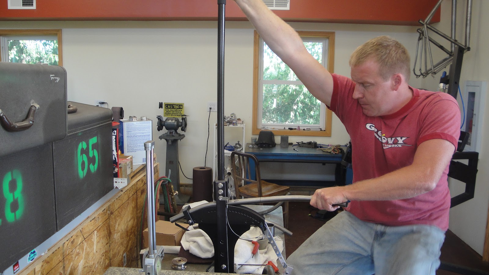
When all the effort is complete, we have a compound bent stay that will accentuate the shape of the front triangle...

As this is a Gates Belt drive bike, one consideration is that the front chainwheel is a much larger diameter than what would be used for a chained system (larger size for greater surface area contact). To insure there is enough room, I need to make a cut out of the chain stay. I fixture up the stay on the horizontal mill and rev it up...

A quick reference on the table to insure the angle and depth are what I need, then a plate will be formed and welded in using a heavier gauge ti.

The stays are welded to the dropouts and then off to the vertical mill to miter in the BB...

The other consideration for a belt drive is that unlike a chain, we cannot take the belt apart to get it on the frame and associated components, so we need to make a passage in the frame. I normally will machine a "gate" passage, but as there are no straight sections to these seat stays, I had to take another approach. I start with a solid bar of 6/4 .875" ti...

After copius machining and time, I have a stepped insert that is tapped to accept a 5mm bolt.


I then machined a mating piece that is bored out to a .120" wall that will be mitered to meet the hooded dropout. The hood will be drilled and chamfered, allowing us to pass a bolt up through and threading the two sections together. Once the upper step is welded into the seat stay, we will have a near invisible point to separate our frame and allow the belt to pass through...

The stay is then mitered and carefully filed to match the curved and ovalized top tube, giving a nice flow and aesthetic...

The top tube is opened up to allow the internal cable routing to pass up through the seat stay, into the top tube, and out the head tube.

The rear end is then welded in place...

I then machined the internal ports to allow for the internal cable routing...

and then welded them into the seat stays, keeping them symetrical, one for the rear hydro line and one for the rear derailleur cable. The third port is hidden under the top tube/seat stay joint.

Ok, with that, the frame is well on the way. The next installment will be on the Ti Unicrown 15mm t/a fork.
cheers,
rody
2 comments:
Very ambitious and nicely done.
Pretty sweet, Rody. Always love your fabrication blogs.
Mount that bender on a wall and your 225lb won't have to work as hard ;)
Post a Comment